Reverse engineering the DVS bus
This post is the culmination of little bits of time here-and-there over the last several evenings, poking around with a DVS brand air handling unit, model DVS-G3 BC220. My aim is partially to share the results - how to talk with the system with a computer - and also to share the process used to figure out the protocol. Maybe I’ll do another post sometime, about what I’m intending to use one of these air handlers for…
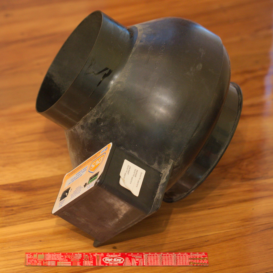
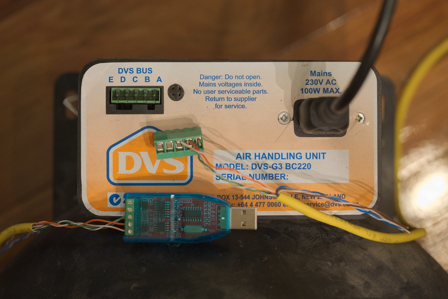
The air handler unit itself is based around a really nice quality ebmpapst fan, with adapters to 200mm ducting on either end, and has some electronics on the side of the fan enclosure. Those electronics provide a C13/C14 mains power connector (the typical computer mains power cord connector) and a standard 5-pin 5.08mm pitch connector which we happen to know carries power and RS485 data. So, it’s easy to hook up to ducting, easy to power, and easy enough to connect your own electronics to monitor or control the data bus. Perfect for tinkering with homebrew HVAC, home monitoring, automation, etc!

The initial investigation was done by my friend Sam, who has a proper DVS installation in his home, and is interested in monitoring various things about his house. He had accumulated some spare bits for a DVS system too, and took those apart to see how they work inside. The basic topology of the DVS Bus is simple - power comes in from the fan, and is clearly provided on the cable to the system controller, because the controller doesn’t have any other power source. Inside the controller is an RS485 interface chip, so it’s clear that the system uses something that’s at least electrically compatible with RS485. With a multimeter then, we can determine the pinout for the “DVS Bus”:
| Label at air handler | Description |
|---|---|
| A | Ground |
| B | RS485 ‘B’ |
| C | RS485 ‘A’ |
| D | +30VDC approximately |
| E | +12VDC |

We also know a little bit about the DVS systems that these air handlers are used in; there can be more than one air handler in a system, there are inline heaters available, the controller can measure the temperature at the air handler, there’s no physical way to set the bus address of the air handler, etc. This told us some things about the data protocol - it had to have some provision for talking to multiple peripherals, it must be bidirectional, the control must be happening in the control box on the wall.
The next step was to figure out the details of the protocol used over RS485. I loaned Sam my logic analyser, and he used it to record a few transactions from the TTL side of that RS485 interface chip. There were some problems with signal integrity which we still haven’t sorted out, but despite those he did manage to get a couple captures which showed 3 different packets being sent from the controller to the air handler, and responses from the air handler.
It’s worth mentioning that the fancy logic analyser wasn’t required for this - we could’ve used an oscilloscope, or simply trial and error to determine the baud rate. Knowing the baud rate, a standard USB-RS485 adapter could be used log transactions with a computer. The logic analyser did make things a bit easier though - it shows the signal over time, which gives the baud rate (4800bps) along with decoded bytes, so you get a good sense of where the boundaries are between packets and that sort of thing.

Serial protocols like this generally follow a format containing some combination of a few standard fields:
Recipient-Sender-Length-Payload-Checksum
We knew that at least the recipient had to be contained in the message, based on the types of systems that the bus can support. Looking at the packets we had captured, there were some strong indications about how the various bytes fit together.
For each transaction, the beginning of the sent and received packets each had the same two bytes as each other - either one or both of those were likely a recipient address. Each of the three types of packet though had a different second byte, which implied that perhaps the first byte indicated the recipient, and the second was some sort of “packet type”. In all the observed packets, the last two bytes often represented substantially bigger numbers than the earlier bytes - perhaps a checksum?
I had a USB-RS485 adapter on hand, so hooked it up to an air handler unit and tried talking with it via a serial port. I didn’t get any response except when I tried repeating packets exactly like the captured ones, so that was further evidence of a checksum in use - if the checksum didn’t match, then the microcontroller in the fan was ignoring the packet, and I was unlikely to guess a packet with a correct checksum.
CRC is a common type of checksum; it didn’t take too long poking around with an online CRC tool to determine that in fact the last two bytes of the captured packets matched with a CRC checksum done over the preceding bytes, specifically CRC16_CCITT. I tried changing a non-checksum byte in one of the first messages, then calculated a new checksum, and sent that to the air handler. The air handler returned a response!
So, at this stage, I could generate valid checksums for any packet data to send to the air handler - time to do some guess-and-checking! The first thing I noticed was that a minimal packet with just first two bytes from a valid packet, plus a matching checksum (so, 4 bytes total) would generate a response with a few more bytes, but the exact number of those bytes varied depending on the second byte. It seemed like a way to query different settings/attributes of the fan - I’ll call those settings/attributes “registers”. A little Python program revealed that the first byte is indeed an address, and the second byte selects a register. Varying the second byte gave varying responses from the fan, but any change to the first byte and it didn’t respond at all.
What are the packet types then, and how do we use them to control and monitor the things we care about? I initially was fairly conservative and tried setting one register at a time, watching for the fan to start spinning around, or for an interesting response over RS485. That approach didn’t yield anything interesting, so I made another program which sent random values to random registers, and let it run - this quickly had the fan whirring away! The next step was just to replay subsets of the random sequence, to find the minimal set to make the fan run.
It turned out, that the fan has one register to control the speed setpoint, and a separate one that, when written, seems to tell the fan to “spin for a little while”. I think of it as a deadman switch - it needs to be written every couple seconds, to keep the fan spinning around a the setpoint.
To figure out the status registers - fan speed and temperature at the fan - I modified one of the earlier programs to continually log the fan’s responses to queries for the known registers, then borrowed a hair dryer…
Anyways, the messages are transmitted at 4800 baud over RS485, LSb first. This is the basic format:
Recipient address (1B), Recipient Register (1B), payload (0+B), checksum (2B)
And, this is the list of registers that I’ve figured out - it’s pretty short, but this is just a fan that we’re talking to…:
| Register | Description |
|---|---|
| 0x3 | Deadman - write occasionally to keep the fan spinning |
| 0x4 | Set address - takes one byte, which becomes the new address of the addressed peripherial |
| 0x5 | Stop |
| 0x10 | Temperature at fan; 3 bytes LSB MSB 0, units TODO |
| 0x15 | Actual fan speed: units TODO |