Casio W-800H Extras
Usually, I wear an old Accutron 214 wristwatch, but the possibility of an upcoming long sailing trip had me thinking that I should get something a little more durable and easier to replace, ideally with an alarm.
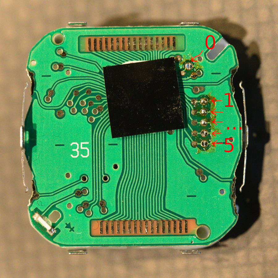
Other than the alarm being a bit underwhelming, I’m happy with my new Casio W-800H, especially following this quick modification to enable a countdown timer! I had seen a reference to adding the timer on the Internet, including a mention of 4 more programmable alarms, but all the documentation on it seemed to be in the form of youtube videos or forum threads mostly full of pictures of dude’s wrists. After some time looking through those, not finding the meaning of jumpers that I’ve numbered 1-5 below, I set out to improve the Internet -just a little- by making some documentation that’s a little more pragmatic:
Casio makes a bajillion watches, of many different models. Within those many models are a few series where each model in a series has similar features to the other models in the same series. By making a small number of different PCBs for the series, and configuring them per watch model, Casio saves lots of engineering effort and manufacturing cost. In this case, the configuration is done via solder jumpers; we’re going to tell the PCB that it’s in a slightly fancier watch!
You’ll need:
- A watch - this is based on a W-800H, but there are bound to be other models with the same PCB.
- #00 philips (it may actually be JIS?) screwdriver
- Fine tweezers or X-Acto type tool, for prying
- Fine soldering iron
- Fine solder and/or wick
Steps
- Take the watch apart, remove the battery as if replacing it.
- The “movement” (I presume that’s what it’s called in an electronic watch…) is a plastic clamshell, with the PCB and battery holder attached to one side, and the LCD attached to the other. The clamshell is held together with a bit of stamped steel - gently lift the steel clips and pry apart the clamshell. The PCB should stay with the battery side of the clamshell, be careful not to pull it away from that side, because there are some tiny springs retained there.
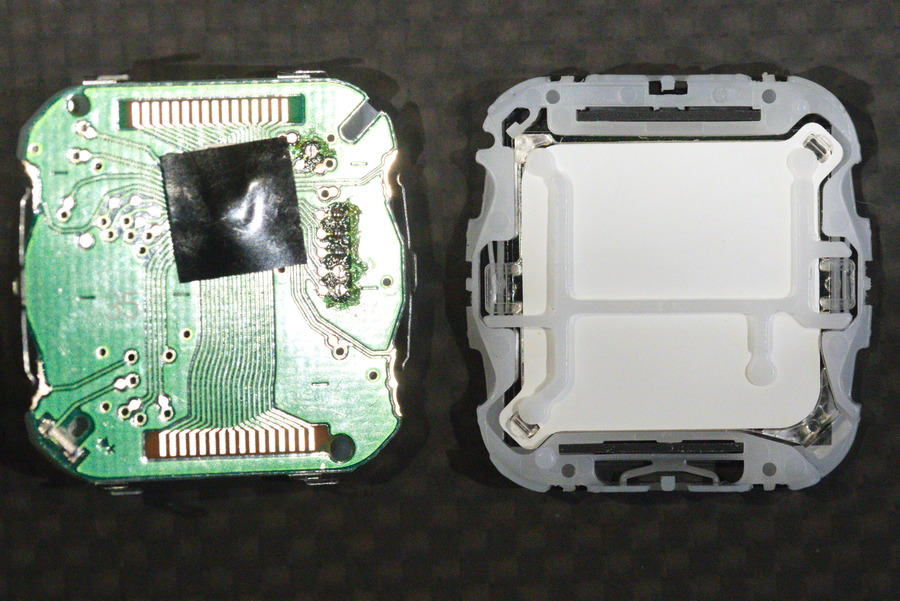
- A white plastic spacer may fall out from between the LCD and PCB, and perhaps one or both elastomeric connectors (rectangular rubber looking thingies that electrically connect the PCB with the LCD). When reassembling, I think the spacer thing is oriented as in the below photo, and the elastomeric connectors drop in to the slots behind the top and bottom edges of the LCD.
- Set solder jumpers as desired - “open” means solder removed, “shorted” or “closed” means connected with a blob of solder.
- Reverse above instructions; you may need to clear the watch memory as the sticker on the battery instructs - I didn’t bother and things seemed to work OK, in the 14 times I reassembled my watch to figure out the below table.
| Jumper number | Effect when shorted | Factory default |
|---|---|---|
| 0 | Timer Disable | shorted |
| 1 | ? | shorted |
| 2 | ? | shorted |
| 3 | 5x alarms | open |
| 4 | ? | open |
| 5 | Dual time disable | open |
Unfortunately, I didn’t consider that some of the jumpers might affect something about the piezo beeper until starting to write this post…
Here’s the top of the PCB, showing the solder jumpers:

Here’s what I think the orientation of the spacer should be; the two sides of the clamshell are opened like a book:
