Voltage Glitch Injection
As a part of my VSP hacking project, I’ve been building a system to read firmware out of Renesas 78K0R microcontrollers, despite it being protected, using voltage glitch injection. Specifically, the system and attack are both described in Shaping the Glitch.
Previously in the VSP project, I had a look at an existing implementation of the same attack, 78K0R Flash Leaker, but decided to try rolling my own. There are a few reasons for this: I’ve got a pretty good arbitrary waveform generator, but not a board that the 78K0R Flash Leaker firmware would run on without modification. I’m also not clear on how much 78K0R firmware I’ll need to read out via this system, and it would be frustrating to spend a fair bit of hobby time on reading out the first few bytes (debug security settings) only to discover that the rest of the flash needs to be read through an incredibly slow process (rather than just a normally-slow process), so that building the faster system was necessary anyway.
Probably most importantly, this is a hobby project and I quite like the idea of the system tuning parameters of the glitch attack to suit the situation. This could be fun to play with, beyond the VSP project!
Status/Plan

On my workbench is a more-or-less set up voltage fault injection system, but there’s a bit of software work still to do. There are basically 3 chunks of code that I’ve been working on, and the combination of them can now (slowly) exploit the ShortChecksum vulnerability. From the top, the pieces are:
- An application that runs on a regular computer, to control the rest of the system. This communicates with the waveform generator (a Siglent SDG2122X) and with the glitch coordinating hardware (Adafruit Metro M4 Express).
- A library for interfacing with electronics test equipment, currently just the waveform generator, over a wired network, but I may add USB support as I’ve had some problems with the network interface on this particular piece of gear. This is separate from 1, because I’ve got a few other pieces of gear that would be nice to be able to write programs to deal with.
- Firmware for the glitch coordinating hardware. In order to precisely time the glitch, I want to generate a trigger pulse for the signal generator at a precisely controllable amount of time after the writing a command to the 78K0R. This works under USB control of the application on the regular computer, and will handle the basic 78K0R flash interface so that flash readout can be run as fast as the target MCU will allow.
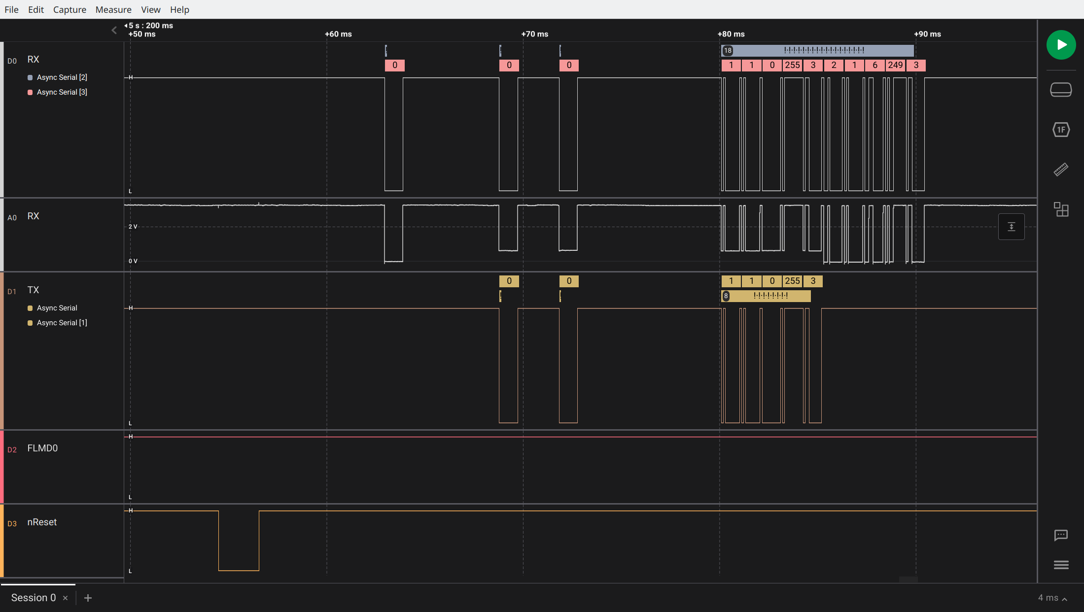
Here’s a “Hello World!” screenshot - the TOOL0 interface line is a bidirectional UART, but the glitching hardware has a typical separate RX and TX line, so I currently have those diode-ORed together for simplicity. But, a nice benefit of this scheme is that the analog RX trace makes it clear where TOOL0 is being driven by the glitching hardware (about 0.5V minimum) or the 78K0R (0V minimum):

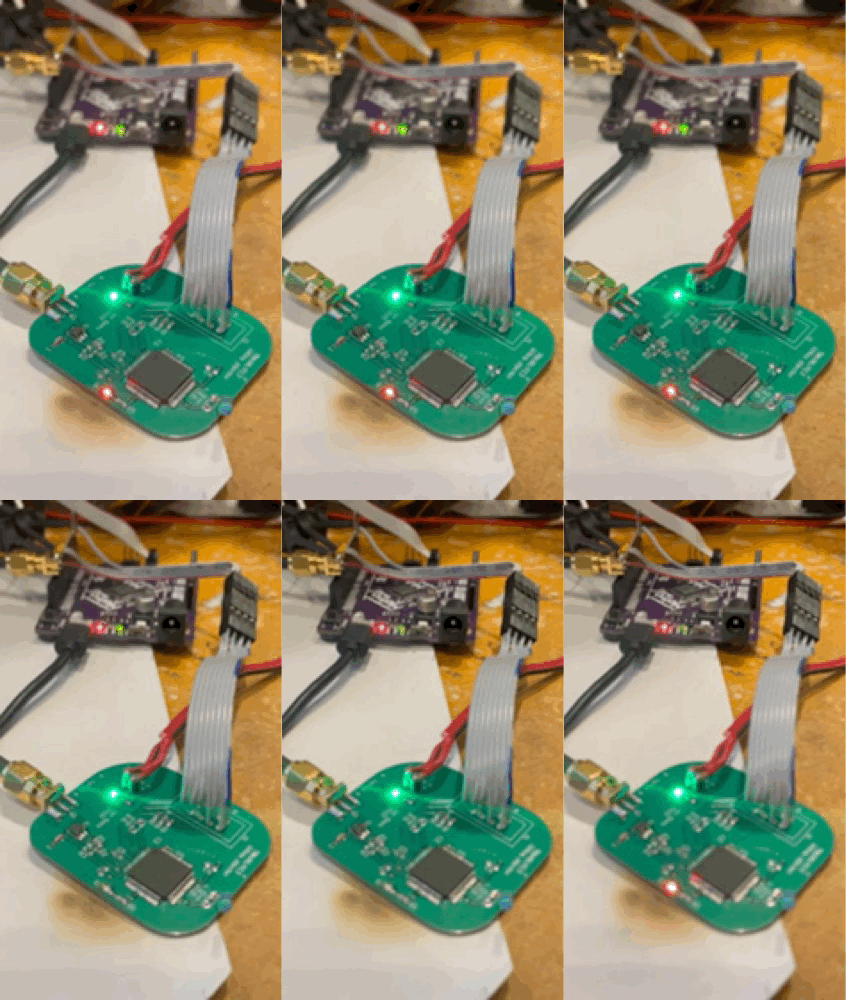
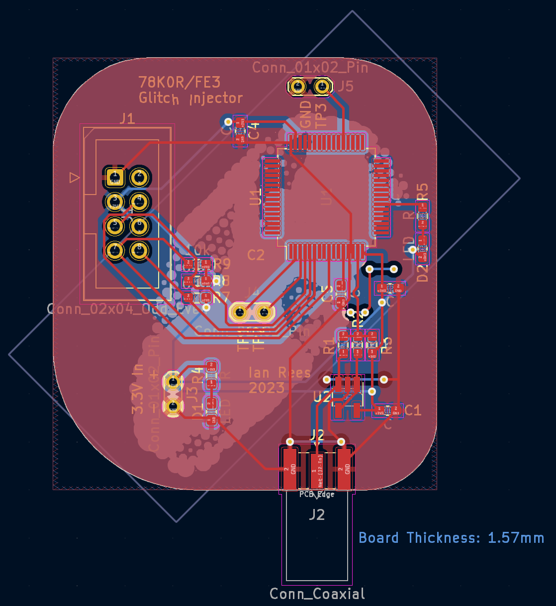
The 78K0R that I’ve been tinkering with has been moved from the Leaf VSP board, on to a PCB that I’ve designed for this purpose, and I have enough software in place that the basics of the attack work. There are several obvious points for improvement, mainly in speeding up the attack, so the next several steps are about doing that work.
When the glitch system is ready, I’ll load some test firmware in this 78K0R (which I’ve already erased the stock firmware from), then try reading it out with this technique. If that works, I’ll repeat the process on a micro that still has the stock firmware that I want to modify!
Background
78K0R supports a feature which optionally enables debugger access via a 10-byte code, but erases the flash if a debugger is connected and supplied with an incorrect password. Both the security settings and the password are stored in the same flash as the firmware. Debugger access would make it easy to read out the entire flash quickly and accurately, but reading flash via the glitch attack will be very slow if it works at all. So, I’ll attempt to read the password via the glitch attack, before moving on to the rest of the firmware if necessary.
Having read Shaping the Glitch, and quickly skimmed over 78K0R Flash Leaker source code that implements an attack from that paper, it’s now clear that the flash dumping operation could be a bit more complicated than “lift a pin, solder in a transistor, program Arduino, retrieve password” which is admittedly what I’d assumed. The paper describes using an arbitrary waveform generator to inject glitches, rather than a simple transistor to ground. Wrapped around the glitch injection hardware and the target, is a genetic algorithm that tunes the glitch waveform parameters. But, that algorithm isn’t described in much detail - perhaps my ignorance of genetic algorithms is showing, and if necessary I’ll study more closely. The authors use this overall technique, which they call AGW, to discover vulnerabilities in the 78K0R, and identify a few approaches to read out data using these vulnerabilities. “SequentialDump” is the most straightforward approach, though slowest, and all are substantially faster to exploit using AGW compared to traditional transistor-based glitch injection.
The Flash Leaker tool seems to implement SequentialDump as described in the paper, but using simple transistor based(?) glitch injection hardware, rather than a genetic-algorithm-optimised arbitrary waveform, so it is much slower than the paper’s approach. Using AGW, I’d expect extracting the complete VSP flash contents (192kB of code and 16kB of data, in the specific part I’m interested in) via SequentialDump could take about a week. That increases to over 3 weeks with a simple glitch injector. These are fairly crude estimates; there will be some amount of blank flash, which will be much faster to read out than the other information. But, of course, I don’t know in advance how much of the flash isn’t blank!
Design
Hardware

The hardware provides a simple unity gain buffer, between the signal generator and the MCU power supply. The buffer is based around a fairly high performance rail-to-rail op-amp, MAX4012. Otherwise, it’s just a simple breakout board for the 78K0R with headers for the programming interface, a few LEDs, and power connections.
I didn’t spend much time on the buffer design, and would do it differently next time. For one; I’d use a current feedback op-amp, as that would be better suited for this application. Secondly, I didn’t pay enough attention to the power supply requirements; although the MAX4012 is happy enough operating from a single 3.3V supply, the input common mode voltage range only goes up to Vcc-2.25V, and with the unity gain amplifier wanting to output 3.3V that creates a problem… Happily, it’s not too hard to re-work the PCB so I can power the buffer from a higher voltage than the rest of the board, but it’s a bit of an unnecessary hassle.
A couple scope captures illustrate the problem, first one showing an input (yellow) and output (blue) signal, with the buffer powered by 3.3V:

Turning the buffer supply up to about 6V produces a much better transfer result:

Running the buffer off a higher voltage supply also reveals another design fault: the input to the buffer is floating unless driven by the signal generator. This means that the output of the buffer can flail around between ground and the roughly 6V rail it now runs on - it turns out that running the buffer at about 6V, given the wide operating supply range of ye olde 78K0R, is OK. But, that would fry modern chips, just to be safe I’ve gone ahead and added a 10kOhm resistor from the buffer input to ground.
I’ve also found that the buffer doesn’t sink enough current to get the 78K0R supply lower than about 1.25V, on a ~10ns timescale. While this isn’t great, I’ve found that making the glitches a bit longer in duration does result in the 78K0R falling over, so perhaps it’s good enough to work as-is. In any case, the next step is in software, so I’ve made a couple measurements to get an idea of what would be required to take the voltage lower if an electronics revision is needed. Yellow is input from the arbitrary waveform generator, blue is output of buffer to the 78K0R:

So, as a bullet-point list:
- Board should take ~6V input, provide variable regulated lower voltage supply for target chip.
- Put some gain in the buffer circuit, to both reduce common-mode voltage requirements, and sharpen edges of glitch.
- Add input termination resistor (50Ohm matching?).
- Limit leakage current through control signals (reset, FLMD0, UART, etc).
- Higher current buffer.
Tuning
Success of a glitch attempt depends on getting the timing and glitch parameters just right; the target chip is of course designed to not do the things we’re trying to make it do! If a glitch attempt is too gentle, the chip will operate as intended - usually returning an error code or similar. If the glitch is too severe, the target will restart (or maybe go in to an error state where restarting is required). Even with the injection tools tuned as precisely as possible, it seems to be a bit of a numbers game with maybe a few thousand attempts required before a successful attack.
If the first step of the process is successfully glitching the target once, the next step is in tuning the system to increase the rate of successful glitches. This tuning includes picking parameters - mainly times and voltages - and also the design of the software and hardware that generates them. Once the system could reasonably reliably exploit the ShortChecksum vulnerability, I let it run for a couple hours at a few different core voltages, to start tuning:
Each of the histograms represents a roughly-equal number of attempted glitches, at a different core voltage setting. The histograms count successful ShortChecksums, at different delay settings (in nanoseconds). Both the voltage and delay settings are programmed in to the signal generator, the delay is after a trigger pulse (supplied by the SAMD51, more below) which indicates that that the last byte of the request has begun transmission.
Serial-to-trigger jitter
To extract firmware from the 78K0R target, I’m using a serial interface to request checksums, verify data, etc - then glitching the target’s power supply precisely as it handles the request. To maximise the rate of successful glitches, it’s essential to maintain tight control of timing from the last serial bit of the request, to the trigger pulse. To enable this precision, both the host-side of the serial interface and the glitch trigger come from the same SAMD51 microcontroller.
In my initial design, the SAMD51 used a SERCOM peripheral for generating the serial signal, and a GPIO to trigger the glitch (the GPIO pin is connected to the signal generator’s trigger input, the signal generator is configured by the host PC). The SERCOM is quite a powerful peripheral, however it is optimised for serial communications, which usually don’t need to be precisely synchronised with some other peripheral…
The SERCOM is designed with a transmit buffer, which the initial firmware took this in to account - it waited for the buffer to empty, put the last byte to be transmitted in to the buffer, triggering the signal generator immediately after. However, due to the way the SERCOM’s internal baud rate generator works, this led to something like +/- 270ns of jitter (at 115200 baud). Clusters of successful attacks in the above histograms are within a roughly 300ns wide window, and crucially those times are settings, not measurements that account for this serial-to-trigger jitter. It is clear that +/- 270ns is far too much.
My next step in improving jitter, and so the overall rate of successful glitches, is to change the firmware to bit-bang the serial signal using GPIO rather than the SERCOM.
A possible further reduction in this latency might be to load the serial request in to the signal generator as an arbitrary wave, and output it over the second output.
Resources
PS4 Aux Hax 2: Syscon - Interesting writeup on PlayStation 4 hacking, which might seem unrelated, but it turns out the micro is an RL78 which at some level is a descendant of the 78K0R. This has a few useful clues regarding the debug port protection features (interestingly, it indicates that the ROM of that chip does check the “erase flash if debug probe password is incorrect” bit, but doesn’t actually do the erase if the password is wrong), and good pointers for attacks using glitching and differential power analysis.
Reverse engineering Toshiba R100 BIOS - a series about another 16-bit Renesas micro, which appears to use a password protection scheme on the debug port like the 78K0R. In their case the debug password scheme was vulnerable to a simple timing attack.
Renesas R01AN1131EU0101 - Application Note describing flash protection and security settings for 78K0R among others.
78K0R Flash Leaker - Arduino project to (very slowly, per docs) read out from the flash, possibly that debug password if the timing approach from the Toshiba BIOS series doesn’t work. My implementation was heavily influenced by this one.
78k0-flash-utility - Python implementation of some of the 78k0 flash interface. Had a few good clues, in particular around holding FLMD0 high to enter flash programming mode.
Automotive Firmware Extraction And Analysis Techniques - PhD thesis of Jan Van den Herrewegen, about 150 pages of excellent material on car hacking, including a section on the Renesas 78K0 (very similar to our 78K0R). And, thankfully open source code including their implementation of the Shaping The Glitch attacks.
