The Battery Closet
My first electric car was a 2014 Nissan Leaf 24X, which I bought second hand in mid-2020. I got the car for a pretty good price, largely due to its battery being a bit worse for wear at something like 71% state of health (SoH - apparently it’s owner in Japan had almost exclusively fast-charged it). This was early enough in the adoption of EVs around here that most potential buyers didn’t have a clear idea of how useful a given battery capacity would be; these 24kWh Leafs with SoH in the 80s or 90s would sell quickly, but cars with worse figures would sit unsold. By my math, a 70% battery would be plenty useful for trips around town, and later experience showed that to be true! At the time, we shared a diesel van with a friend, which would be fine for longer trips.
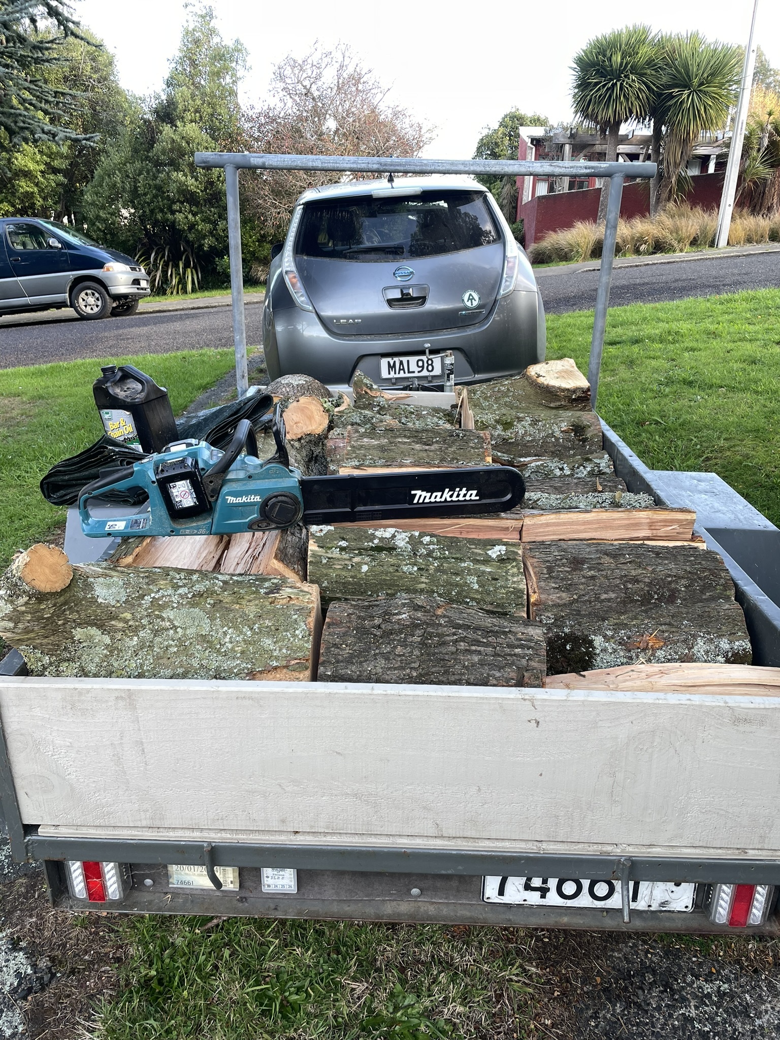
A couple years later, I’d added a trailer-rated towbar and the Leaf was my favourite car ever. My friend J bought a Leaf just like it, except his had a battery that was in much better shape, and the car had been in a crash and writen off. J wanted the crashed car just for the motor, the battery pack was perfectly intact and wound up being a nice upgrade for my car! That left me with a pretty good battery pack, just a percent or two lower SoH than when I bought it as we’d taken much better care of it than the original owner. Time for a house battery!
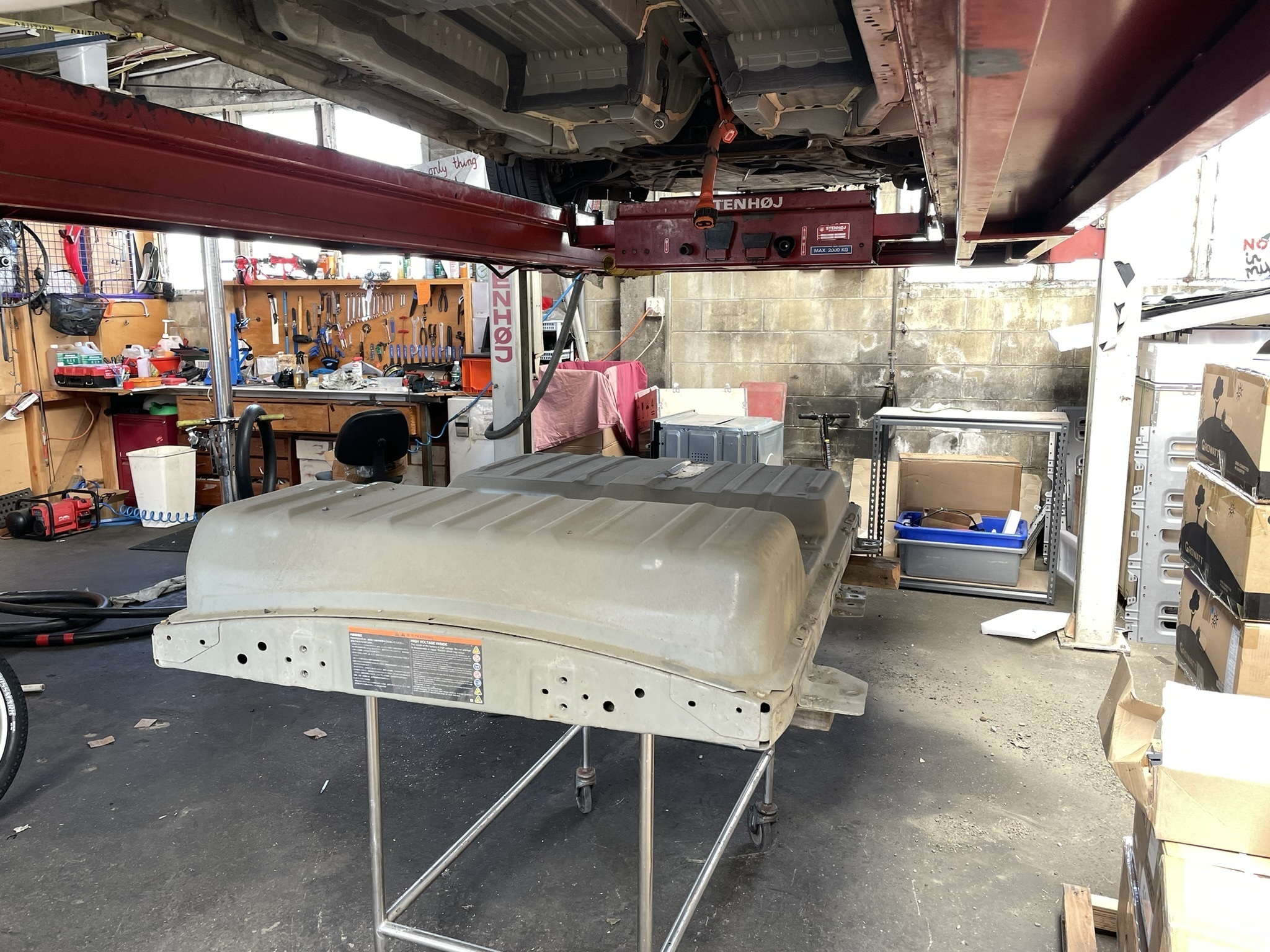
Things sat in this state for about 2 years. I’d broken down the Leaf battery pack and had carefully stacked and re-stacked 24 modules in a couple corners of the basement as requirements shifted; the other 24 modules were still bolted together in one big lump that I shuffled around in the 2D plane of the basement floor. Forward movement on the house battery project required making several decisions before work could start, some were about the house electrical system, but the main hangup was where to put the battery itself. This type of battery is capable of catching fire; it’s unlikely to happen but if it did I’d rather it not be catastrophic.

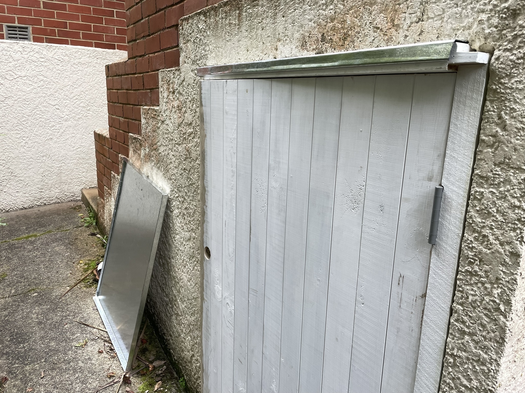
More recently, the city council changed our waste collection scheme, and the new set of wheelie bins no longer fit in the little concrete cubby where we used to keep them. That cubby is a under a set of concrete stairs, has three concrete walls, and it’s not too far from the main house switchboard. Crucially, there’s a substantial amount of concrete between the inside and the wood framing of my house…
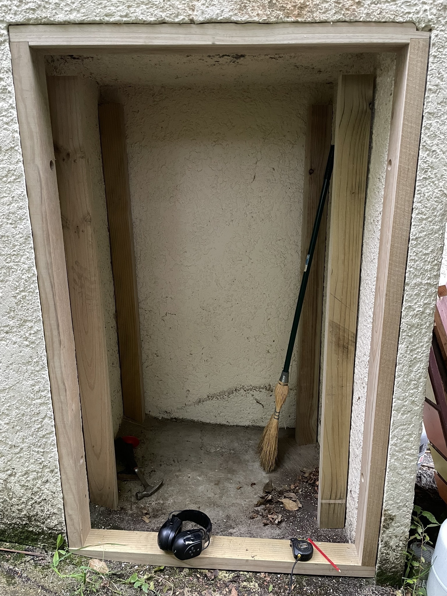
Construction began with building a door to turn the cubby in to a closet. I used H3.2 treated pine (the treatment is a solution containing copper, chrome, and arsenic - not very nice to the skin), rough sawn and wet, as it was a fraction the price of the kiln dried or especially the machined tongue and groove stuff. I left the wood stacked it in the basement for a while with stickers between each layer and the dehumidifier on, and that seemed to help a little. Since the door would be in a somewhat shady and damp area anyway, I figured there might be less issues with expansion/contraction starting with wood on the wetter side. The opening in the concrete is impressively square on the top and sides, but the bottom piece in particular took a bit of shaping. Expansion bolts hold the sides of the frame in to the concrete, and the corners are locked in place with joints and screws.
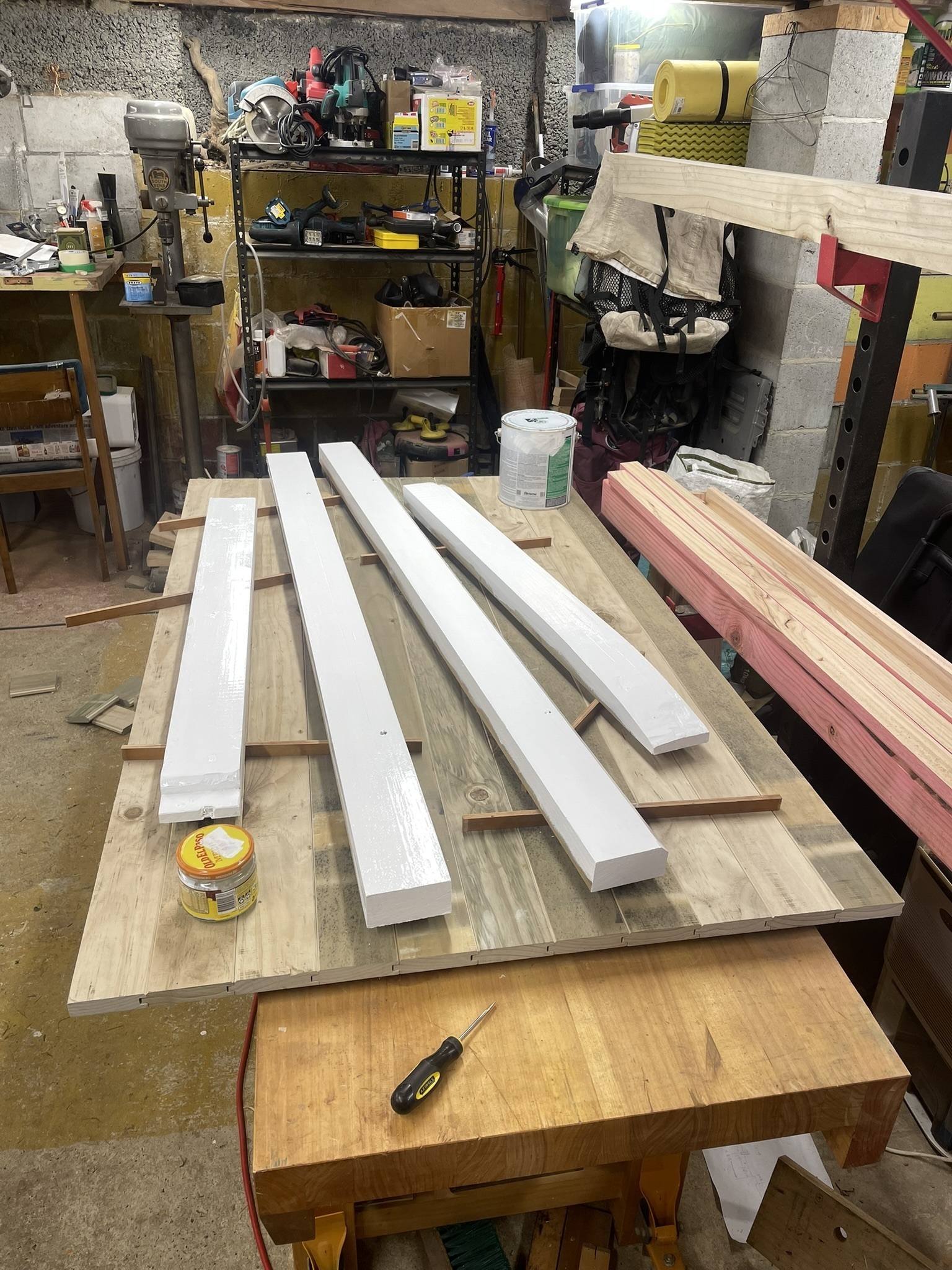
The door itself is a straightforward tongue, groove, and V panel, intended to match the existing basement door. I cut the tongue and groove on the table saw (which needs at least one bearing replaced, maybe in another post!), and made the V chamfer with a hand plane. Once the frame fit nicely, the sides that wouldn’t be accessible after installation got a coating of paint. Fitting the door went fairly smoothly over a few iterations, I fit a deadbolt and carved a pull handle out of a wood offcut, then put a coat of paint on the outside leaving the inside exposed wood so it could dry out quicker.
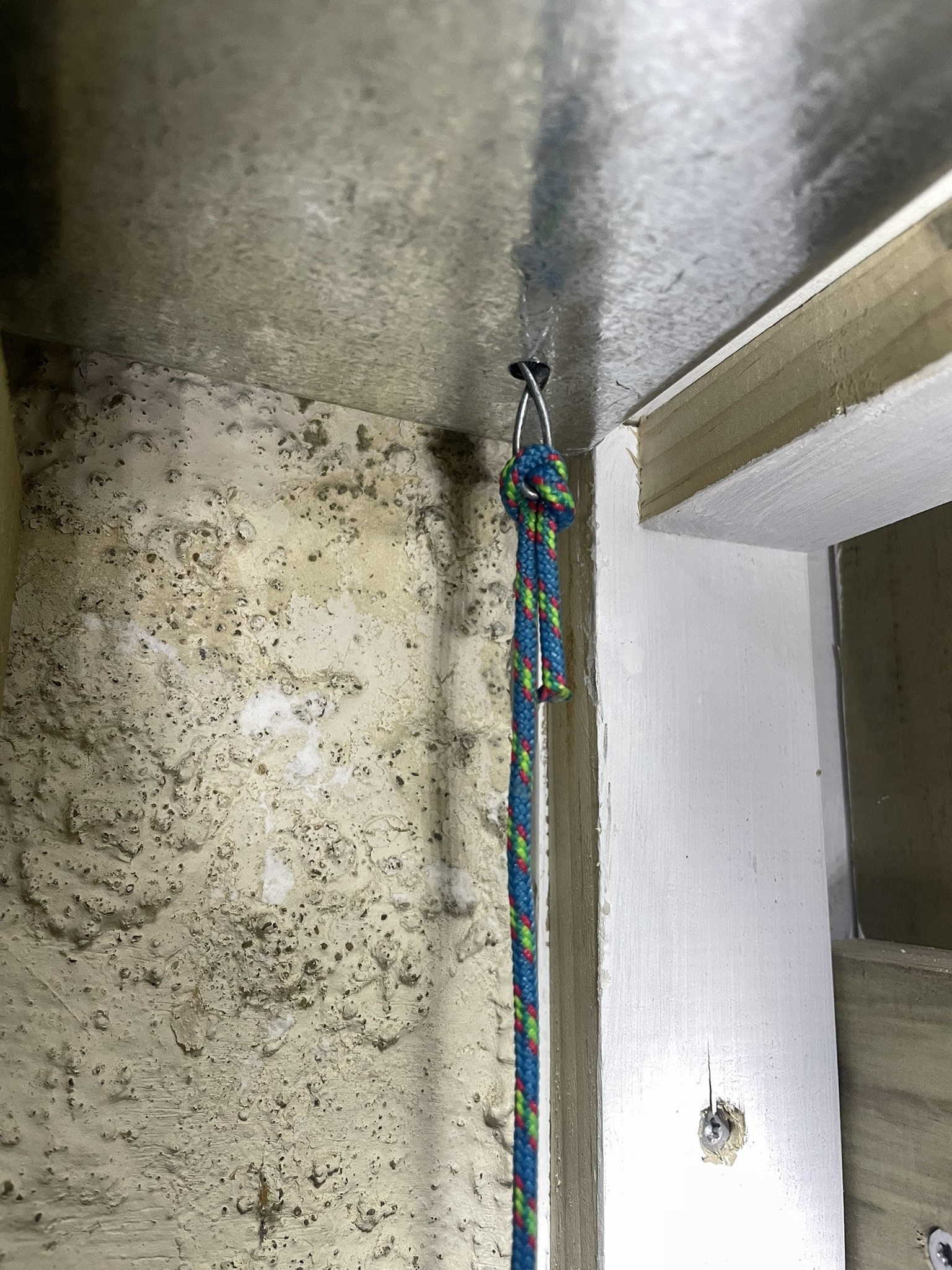
Sometime in this door fitting period, we had a rain storm and I realised that the concrete roof of the cubby isn’t completely watertight. The stairs above it are only partially exposed to the sky (pro tip: eaves are an important house feature) but there’s a crack in the steps, and a heavy enough rain results in dribbles inside. My plan is to attempt to fill the crack, maybe even paint the stairs, to seal it from the outside, but regardless I used J’s bending brake to make an internal roof and flashing from some galvanised sheet steel. The flashing drains in to the roof, and the roof drains in a front corner where there’s a gap under the threshold guided by a hanging bit of cord. This seems to work well, though I might enlarge the hole a little so surface tension doesn’t bridge the whole hole.
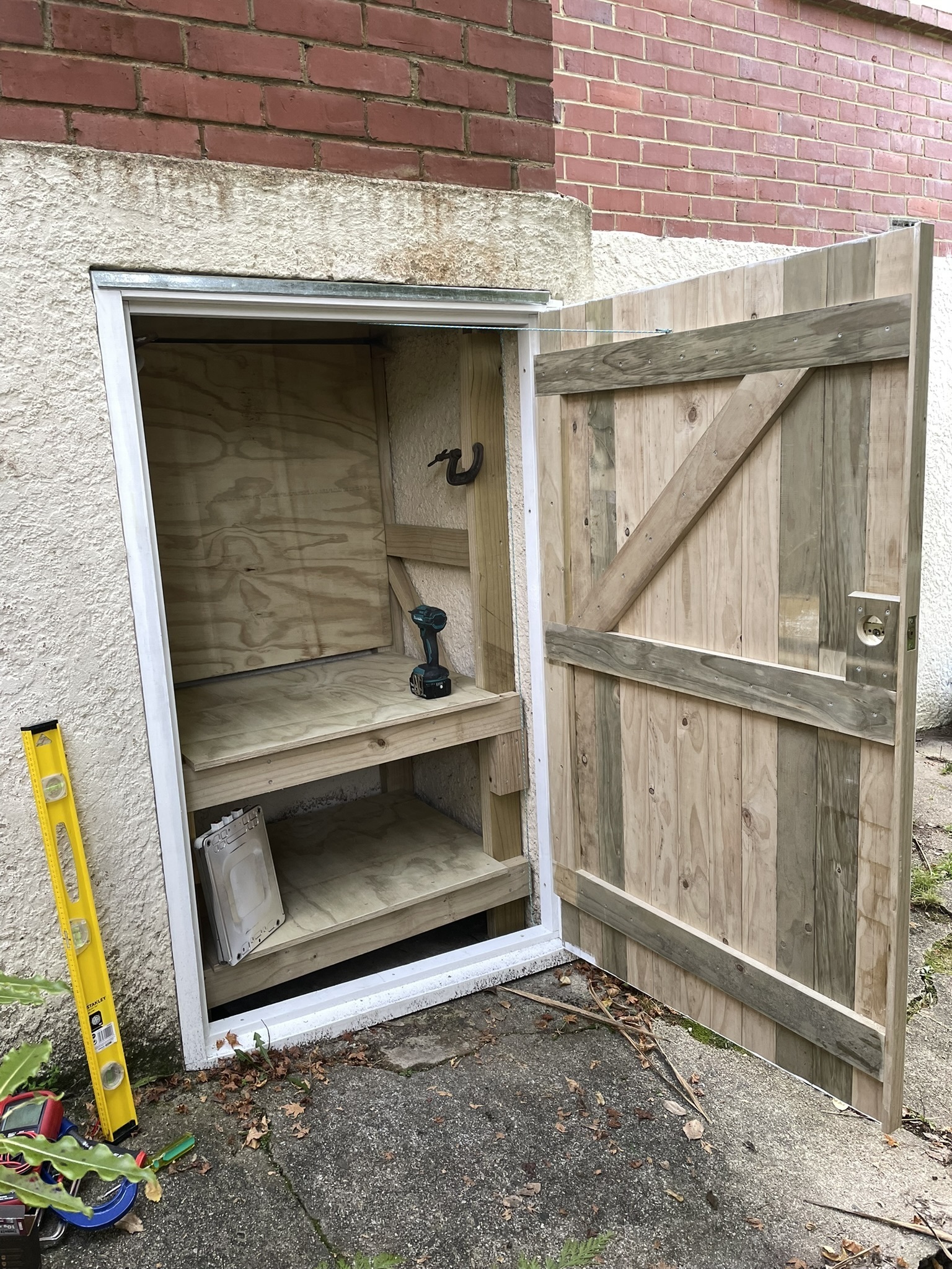
The shelf posts sit on pads of damp proof barrier, diagonal braces on either side resist tipping front-to-back, and side-to-side movement it is constrained by the ply backing panel where the inverter will mount. The shelves are sturdy and simple things, made with ply above a frame of 100x50 (four by two, in the old units). The top shelf is removable and the bottom one is fixed. Originally, I intended to fix the top shelf too; steps in the posts would carry the weight and it would be held in place by a couple screws thoughtfully located so the shelf would be easy to remove. But, as I test fit the shelf ply, I realised that the frame was already constrained from moving in three directions by the walls and the posts, and the ply could be made to hold the frame in the fourth direction - it’s easy to remove with no tools!
With the space prepared, it was time to start on the electrical. Cars like the 2014 24kWh Leaf use a battery pack made with 48 modules, all in series to make roughly 400V. Each module is what I’ve learned is called a 2s2p arrangement - two series pairs of two cells in parallel. So, each module has two sturdy connectors to handle the bulk current (the motor shaft output is 80kW, so the battery terminals handle roughly 200A) and a central connector for the battery management system (BMS) to monitor and balance the charge of each parallel pair. Based on J’s suggestion - back when we did the swap that started this whole exercise - I’d buy one more module and wire them together in what I guess is a 7s7p (or is it 7s7p2s2p?) arrangement to make a “48V” pack (quotes as the actual voltage is more like 58V when fully charged). If I were to start this exercise over again today, I’d be tempted to find a 400V inverter and leave the Leaf pack intact, but here we are!
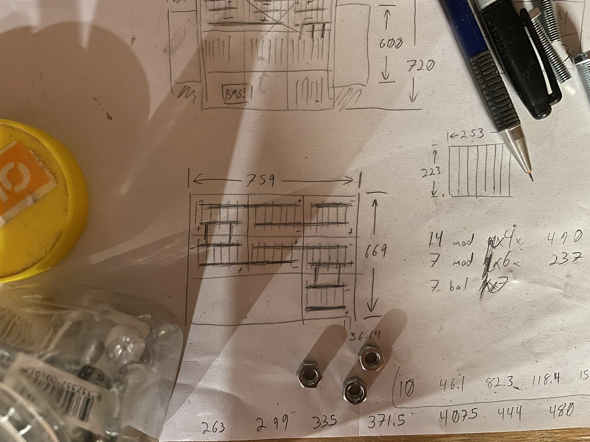
With 49 modules, each with 3 terminals, there are a lot of connections to be made in this battery pack. In order to make that a bit more tractable, I wanted to orient the stacks of 7 parallel modules together so they could be connected using three straight bus bars. Very luckily, the cubby dimensions resulted in a shelf that’s a perfect width for 21 modules oriented like books on a library shelf. 21/7 = 3, so three of these stacks would fit neatly across the shelf, and there’s enough space for three rows front-to-back! Some of the modules were slightly thicker than others (I believe just because they’ve been on a not-perfectly-flat basement floor for a couple years), so I made this design with a little bit of tolerance, but it’s snug enough that any problematic swelling in the pack should be apparent.
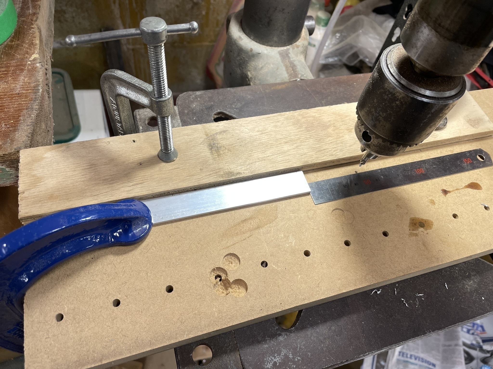
Bus bars were hacksawed from some aluminium flat bar, then I used the drill press with a fixture to locate the holes in them, and finally deburred with a flat file and a countersink in a handheld drill. When doing repetitive work like this, and particularly when it needs to be done accurately, it really pays to spend a few minutes thinking through the process. This time, I used a bit of scrap MDF to put the drill on the centre line of the alloy bar - that stayed in place for all the bus bars made with that size stock (the bars that connect the balancing terminals are less chunky as they only need to carry a couple amps at most). Then, for each hole, I’d carefully set a stop to position the hole lengthwise, and run each bar through with the centre drill in. After centre drilling all the bars, I removed the lengthwise stop (but not the widthwise one) and replaced the centre drill with a twist drill to go out to the final diameter. One handy technique I used here is to mark each bar so that it is always oriented the same way in the fixture. Doing this minimises any error in eg the length of the bus bars, by always referencing from the same surfaces.
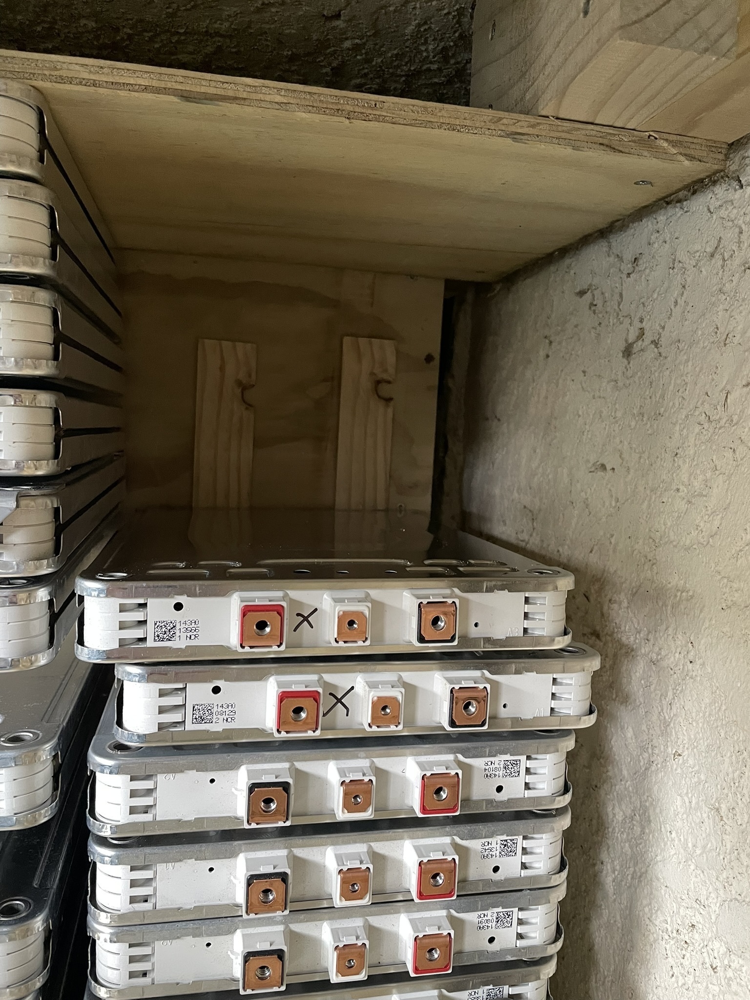
With a pile of bus bars made up, it was time to start assembling the battery pack. J has done a fair bit with recycled Leaf batteries, and said that the 24 modules at the rear (which are bolted in to one big stack, this is the lump in the battery pack closer to the camera in the second photo) tend to be in slightly worse shape than the others, so I marked them before disassembling the Leaf pack, and mixed the marked ones throughout the house pack to even out the capacity of each stack of 7 modules. While doing this, it became clear that an assumption I’d made wasn’t quite right: some of those rear 24 modules had a slightly different mounting bracket, which made them sit a few mm higher on my shelf. A quick feeding of some scrap wood to the table saw produced some shims to lift the shorter modules up, putting the terminals all in the same plane.
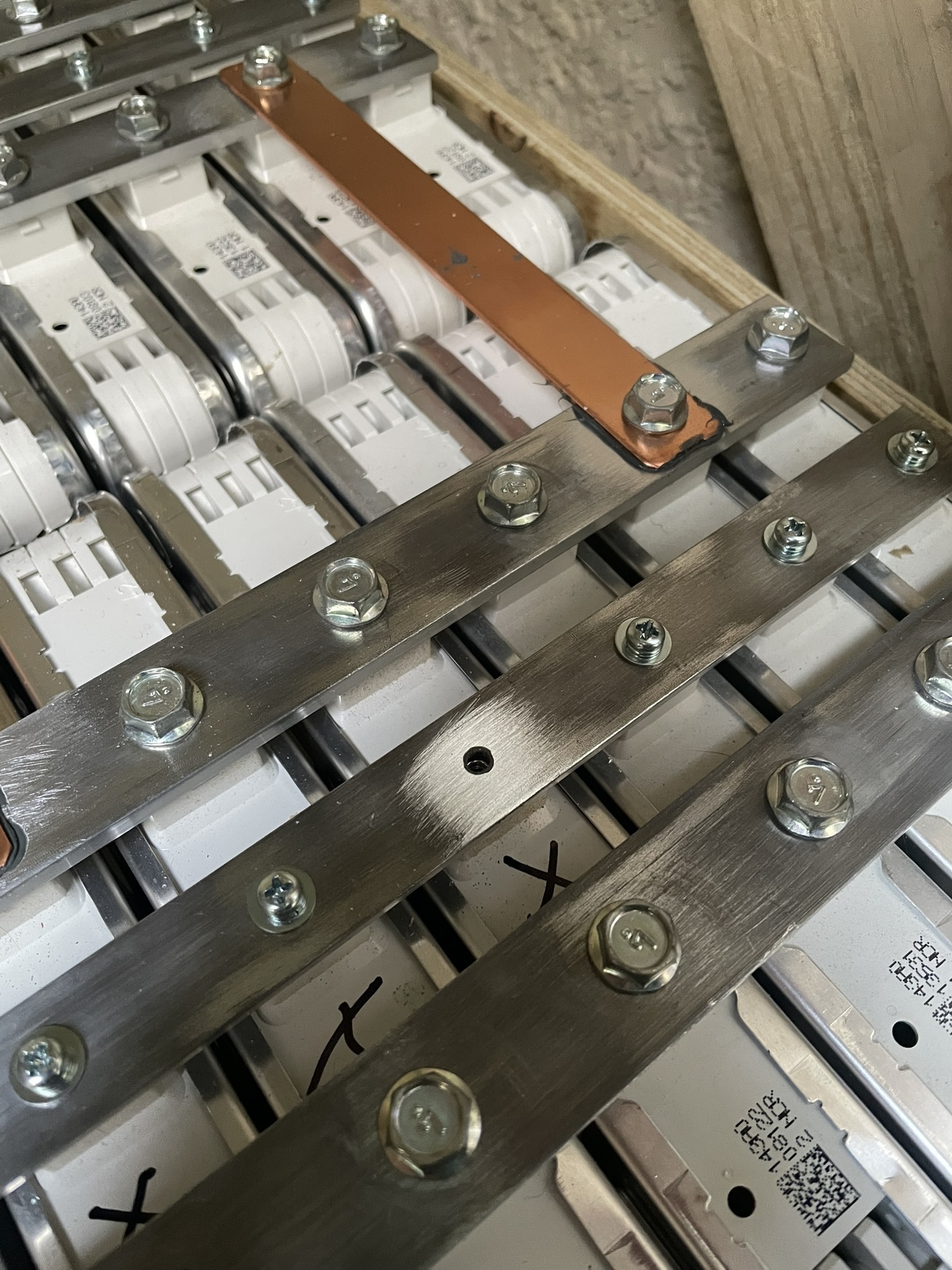
The choice to use aluminium bus bars took a bit of thought. Copper is a significantly better electrical conductor than aluminium, but it’s also much more expensive, harder to source, and harder to work with. Aluminium is quite reactive with oxygen and aluminium oxide is a good electrical insulator, so when making electrical connections involving aluminium it’s important to clean the oxide off immediately before making the connection. There’s also a risk of galvanic corrosion when two dissimilar metals - such as the copper terminals and aluminium bus bars - are connected if the joint could be exposed to moisture. To help alleviate both these concerns, immediately before bolting each joint together I wire-brushed both surfaces then applied a bit of a compound called Alminox. In the Leaf pack were a few copper bus bars of just the right length to connect adjacent rows of modules together; by using these instead of aluminium I can easily inspect a few aluminium-copper connection as needed. It is remarkable how quickly aluminium oxides - the above photo shows a bus bar that was entirely wire brushed just a few days earlier, and a shiny patch I’ve just re-brushed in preparation for a connection for the BMS.
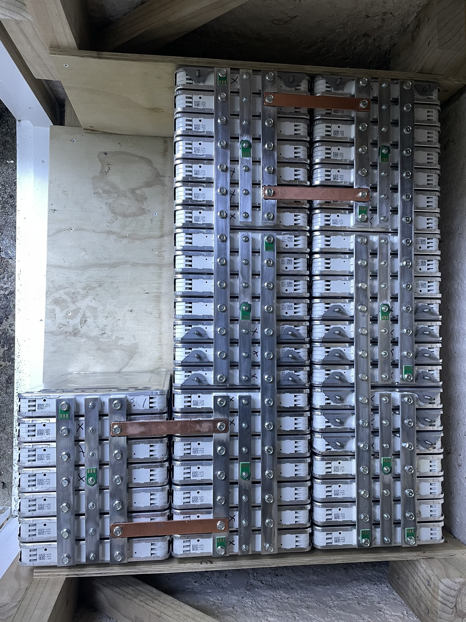
After carefully bolting all the bus bars in place, I attached little bits of circuit board to each parallel connection. These bits of circuit board will make it easy to solder on wires to the BMS once it arrives. The BMS will use these connections to monitor the voltage of each cell, and to source/sink a bit of current as needed to keep the cell voltages in balance. A good BMS is absolutely crucial with lithium-ion batteries, as over or under charging a cell can lead to fire. So, as tempting as it might be to hook up the big cables, the pack will wait at this stage for a BMS.
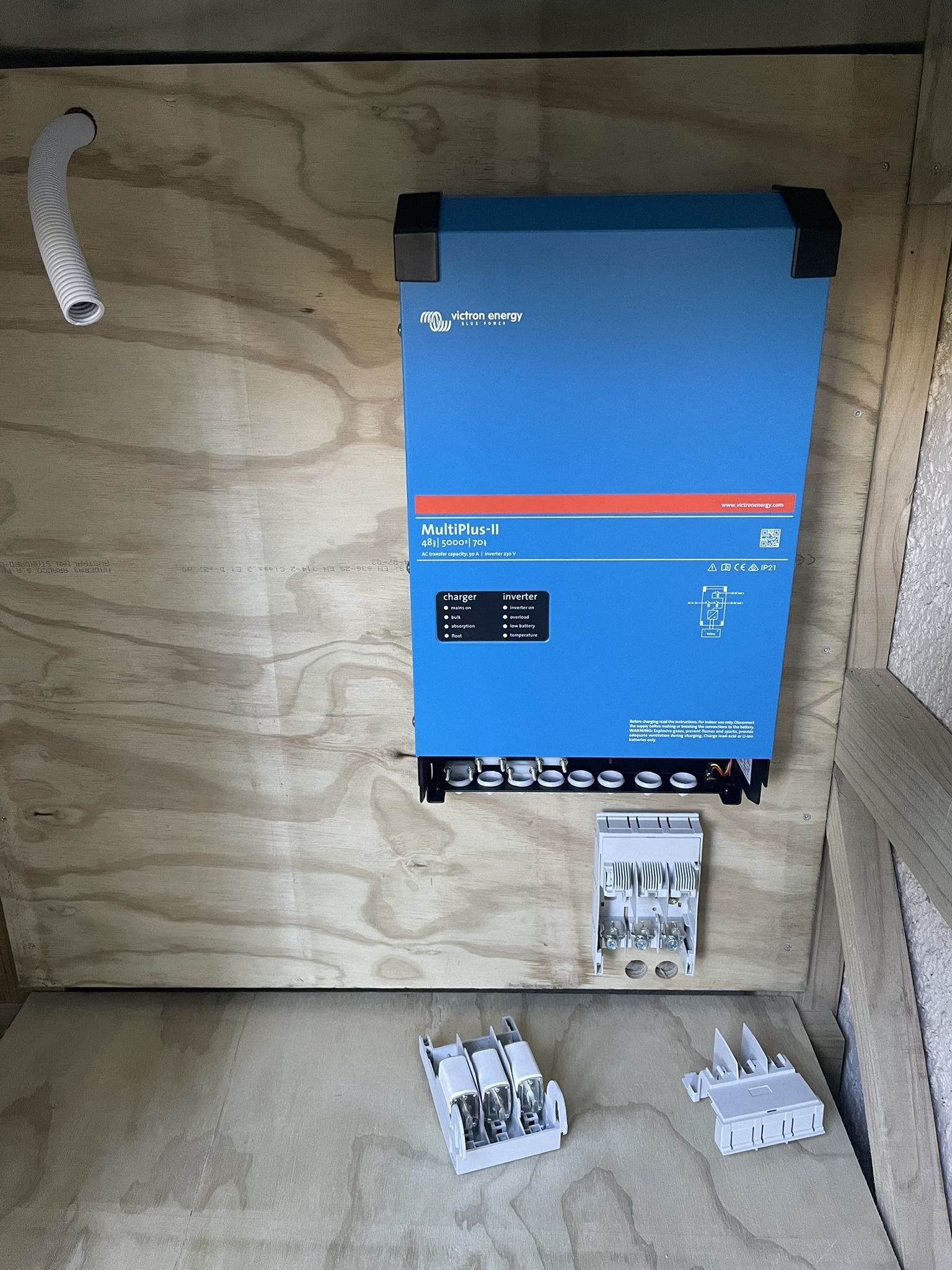
The inverter is a Victron Multiplus II, which I’ll certainly discuss in more depth later on. Mounting it is straightforward - there’s a stamped metal bracket that screws to the wall, and the (surprisingly heavy!) inverter hangs off that, with a couple screws securing the bottom. I went ahead and mounted a fused disconnect, this one is designed for 3 phase AC applications so I’ll just use two of the fuses. It appears I’ll be able to recycle two chunky cables from the Leaf pack between the fused disconnect to the battery pack - convenient! But, I don’t have the right tools for crimping fittings on to that size cable, will borrow some in the coming days.