Prototyping with PCBWay
For my pig trap project, I needed to have some circuit boards made, and decided to try a different supplier from my usual. PCBWay had been in touch previously after someone there noticed the somewhat-embarrassing KiCad Halftone program that I used to start learning Rust. They offered me sponsorship - essentially these boards would be free of charge, including the stencil, in exchange for this blog post which has taken me far too many months to actually write!
The ordering process was really smooth, the PCBWay order form provides tons of options, I particularly liked being able to select lead free boards. Even though normal electronics manufacturing has been lead free for ages, the norm has been that inexpensive prototype PCBs are made using Hot Air Solder Levelling (HASL) finish with old school lead tin solder. They’re durable and easy to work on, but I felt it was time for me to transition to lead free - PCBWay made it easy.
Regular status updates through the manufacturing and shipping process kept me informed, it was no surprise when the boards arrived. And, they look great!
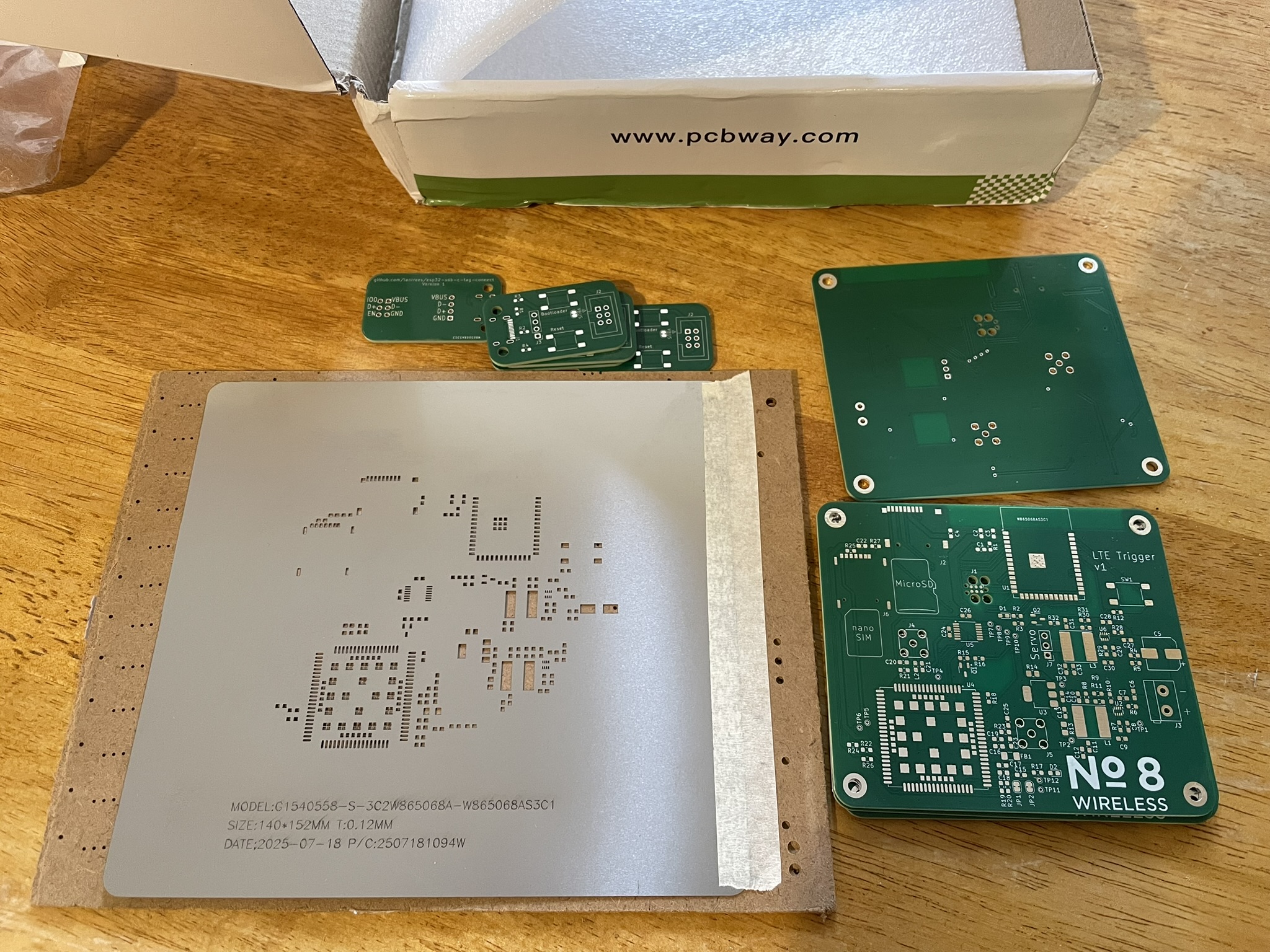
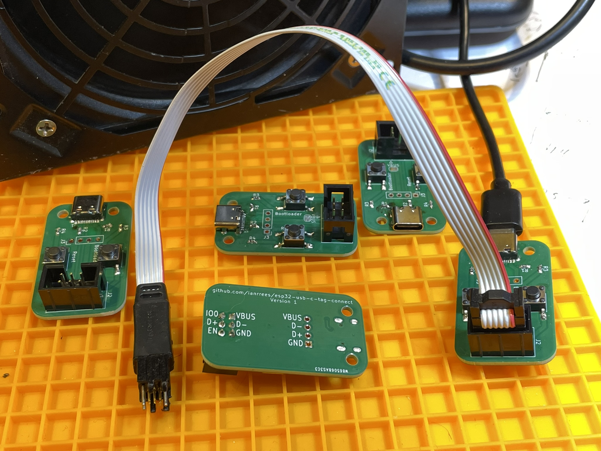
To begin with, I assembled some development tools - these have a USB connection on one side, and a 2x3 pin header to suit a Tag Connect cable that I’ll use for programming the ESP32s3 microcontroller. The design for these boards is on GitHub.
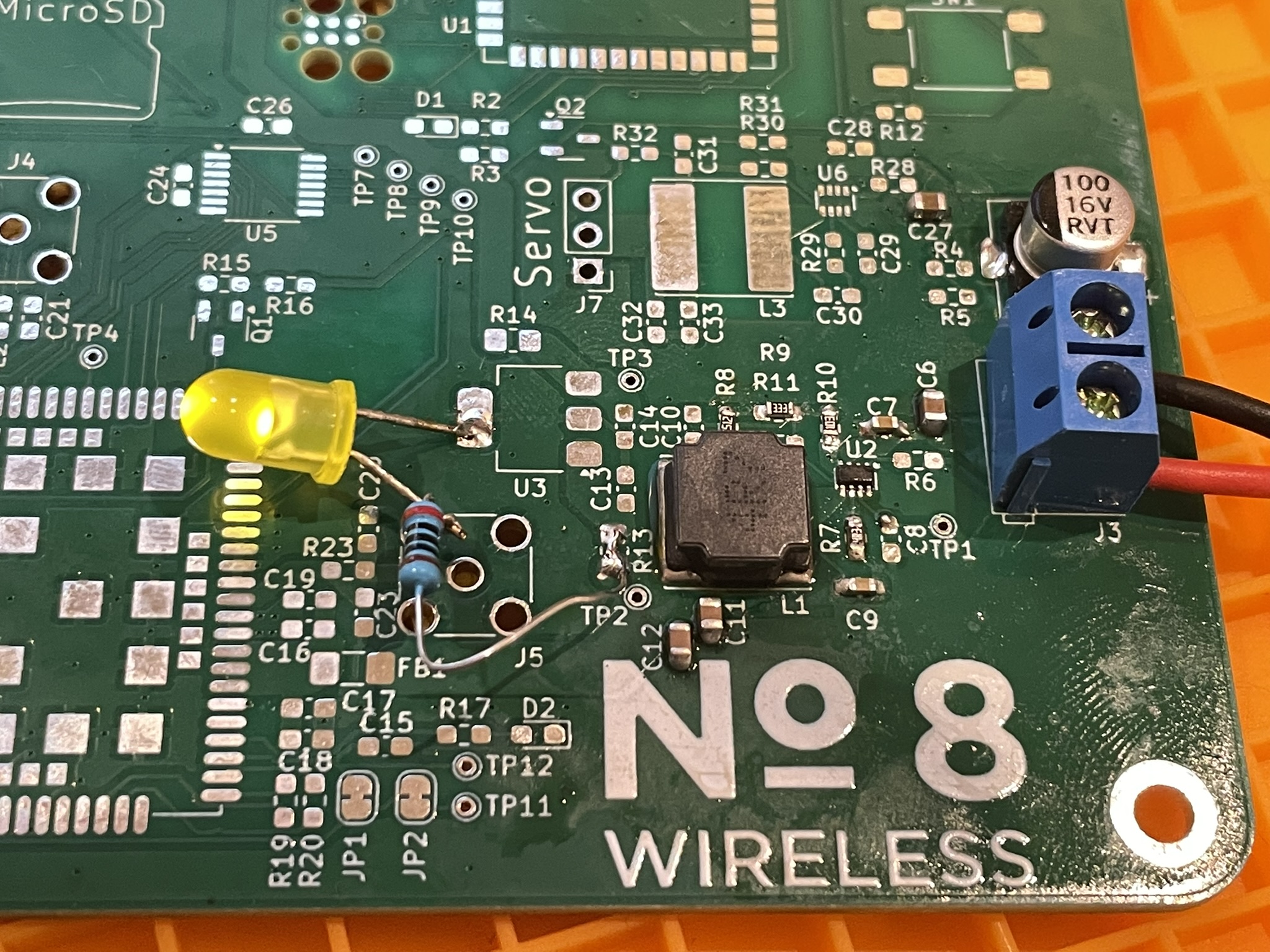
On the main boards, I first brought up the power supply. This design has two very similar buck converters built around the Ti TPS6293x, which seems very easy to use but it’s a new part to me, and of course nothing else on the board is usable without a power supply! In assembling this, I noted down the first change to make in the next PCB rev: pick a better inductor footprint!
I proceeded to populate the rest of the board, and was pleasantly surprised to find the µSD and SIM footprints both match, including the somewhat laboriously drawn card orientation graphics (which I’ll put on GitHub).
The LTE module didn’t immediately power up as designed, after a bit of troubleshooting, I realised that I’d somehow put the reference designators of two nearby resistors the wrong way around, so had assembled the board with far too low a resistance in one position, and far too high in the other.
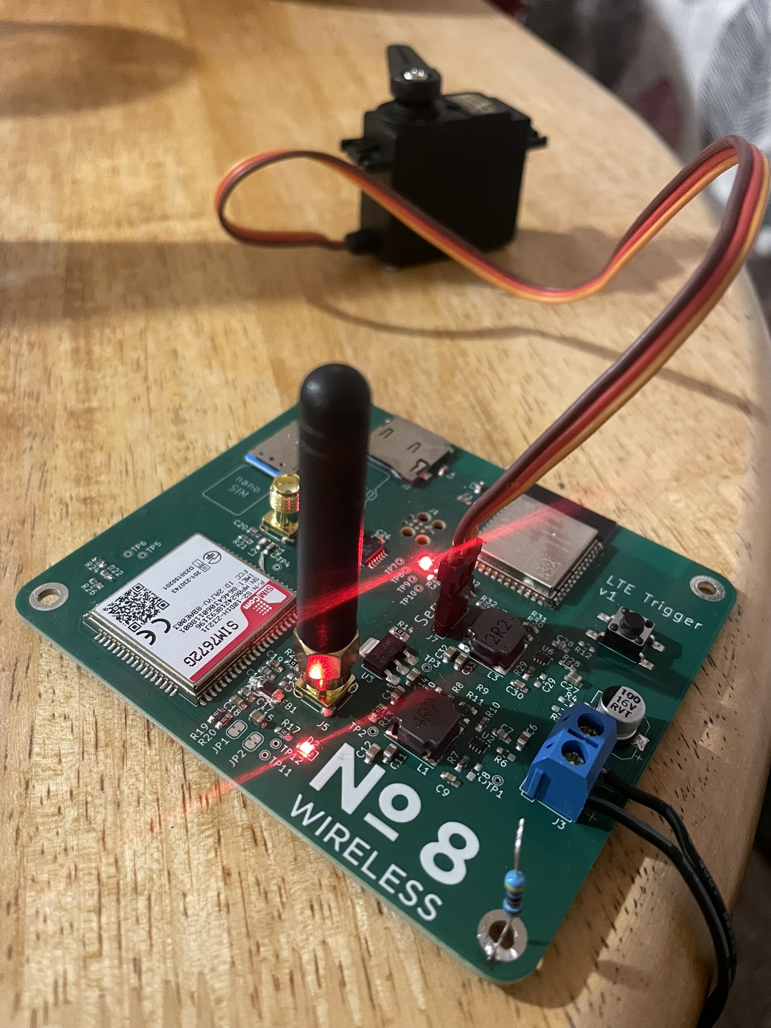
With the resistors swapped around, I got blinkenlights! On to firmware development.